Hacking Chinese LEDs for Controller Compatibility

It’s taken a long time, but my LEDs are finally on the tank!! YahoO

For those who don’t know, I started this conversation in my intro thread. Here is the general idea:

[quote=“bnelson, post:8, topic:6373”]

[quote=“reefman66, post:4, topic:6373”]
:Welcome) to DRC Bryant. Even pics from the old tank looks good. Please do post some current ones too.

What do the D120 led fixtures look like? How are you planning to hook it up to a controller?[/quote]

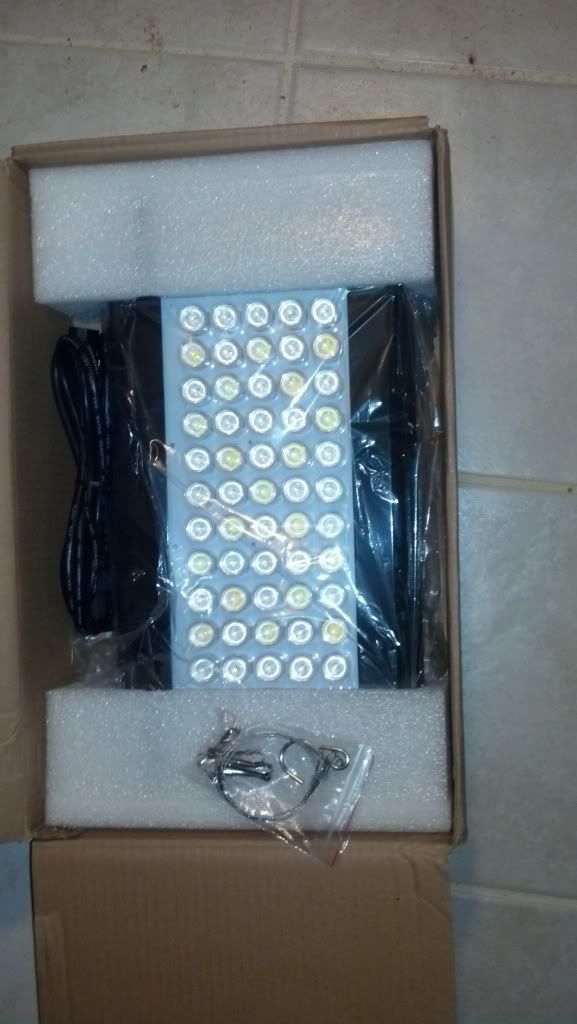
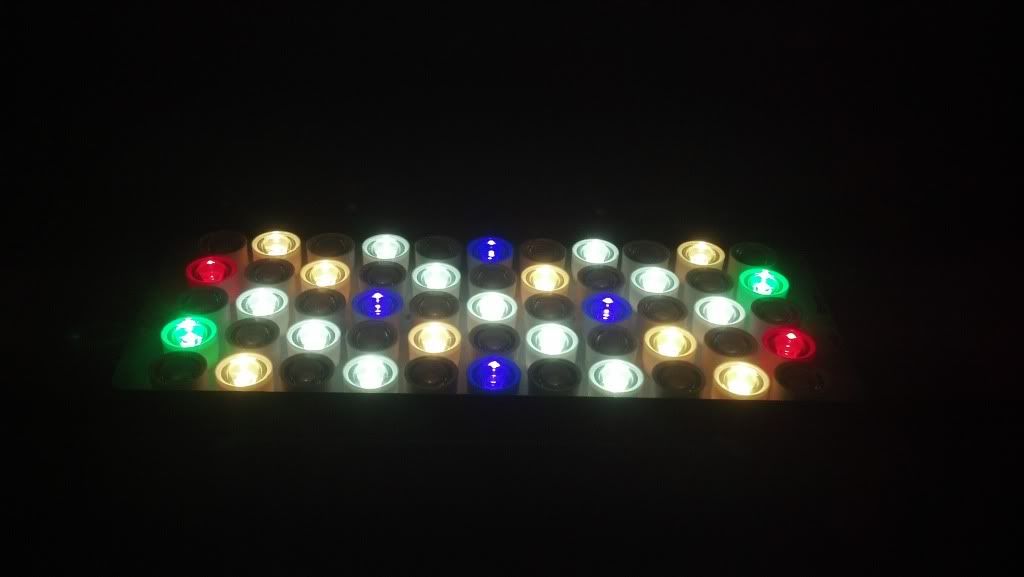
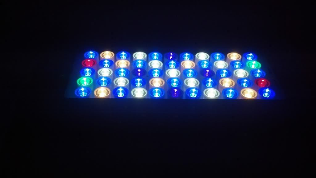
Here are some pics of the fixture. I got it off alliexpress.com. They are your typical Chinese dimmable led fixture with 90 deg optics and cost $170-180. What’s great though is these fixtures were completely custom. I just sent them a layout and that was that. I ended up with 14 blue, 14 royal blue, 4 violet, 2 green, 2 red, 8 3500K and 11 6500K.

The fixture came with nobs for dimming, but I want to do a sun rise/set program with a lunar cycle. So I took the fixtures apart and was shocked at the quality inside, everything was laid out well and they were even using Texas Instruments ICs. The downside though is that the drivers only take in 0-10V control signal not PWM that most controllers output. So I have 2 options to hook them up. The one I’m currently pursuing is to just buy some brushed speed controllers for RC planes/cars. I’m just going to buy 2, one for each channel. These take in a pwm control signal and output an analog voltage. This option is simple and takes the least amount of work. The backup plan is to make my own simple circuit which would consist of an RC low pass filter (converts pwm to analog) and an op-amp (takes the 5V from the board and gains it to 10V). I’ll keep you guys posted as things progress. I’m trying to pull this off before the swap.


[/quote]

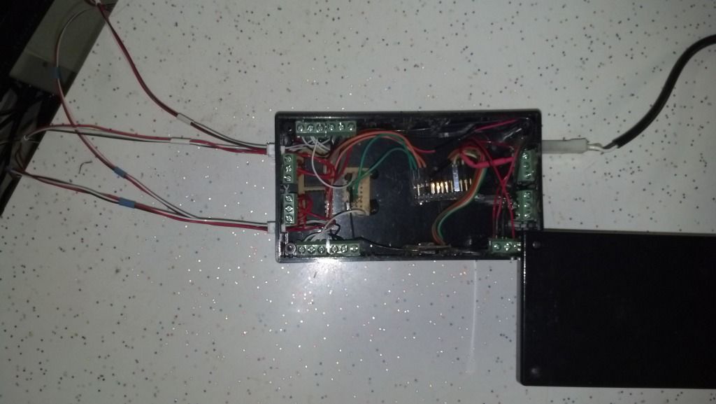
So I tried a bunch of different methods before I realized that the control line was outputting 10V. There must be a resistor in the ballast pulling that channel up to 10V, so i needed to sink the power not send it power. All I needed to do was throw in an NPN transistor and feed it a 5V pwm signal from my arduino. :BB) Additionally, my ballasts required a 10V on/off signal to kill the lights at night. So I popped in a relay and boom, I’m done. PBJ! Here is what the control box looks like. I’m using an arduino pro micro, but anything with 2 digital outputs, 2 pwm outputs, and is I2C capable will work.

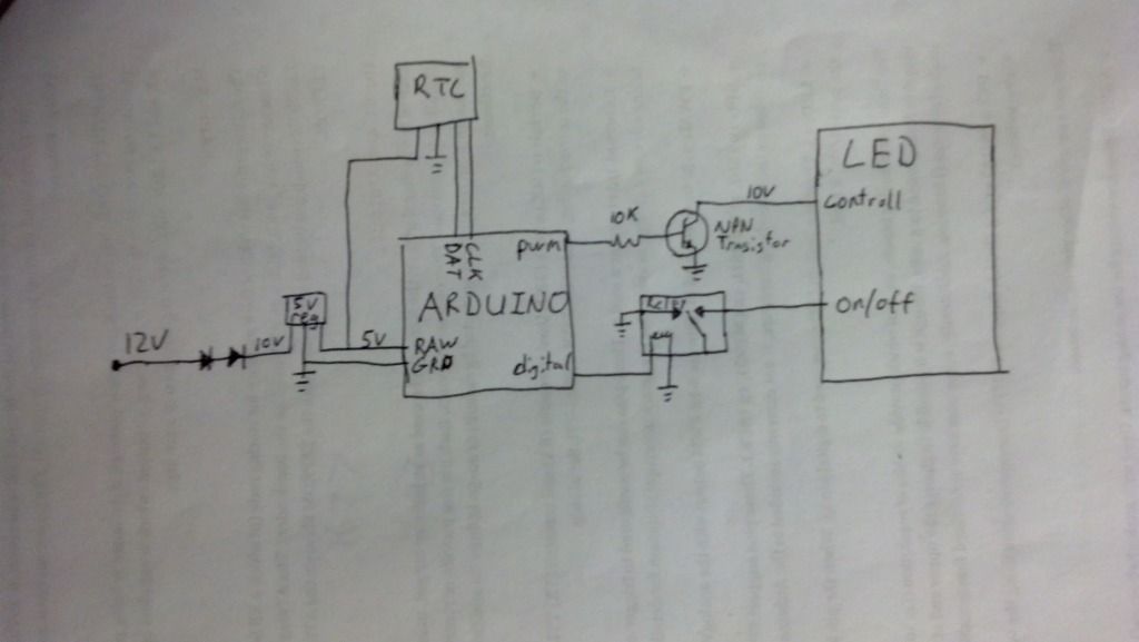
Here is the schematic if anybody is interested. It’s important to note that I drew the default relay setting wrong. You have to power the relay for the lights to turn on. I didn’t want my controller to fail and have all the fixtures blast my corals. This way, if it fails, the lights turn off. The arduino is also connected to a Sparkfun real time clock.

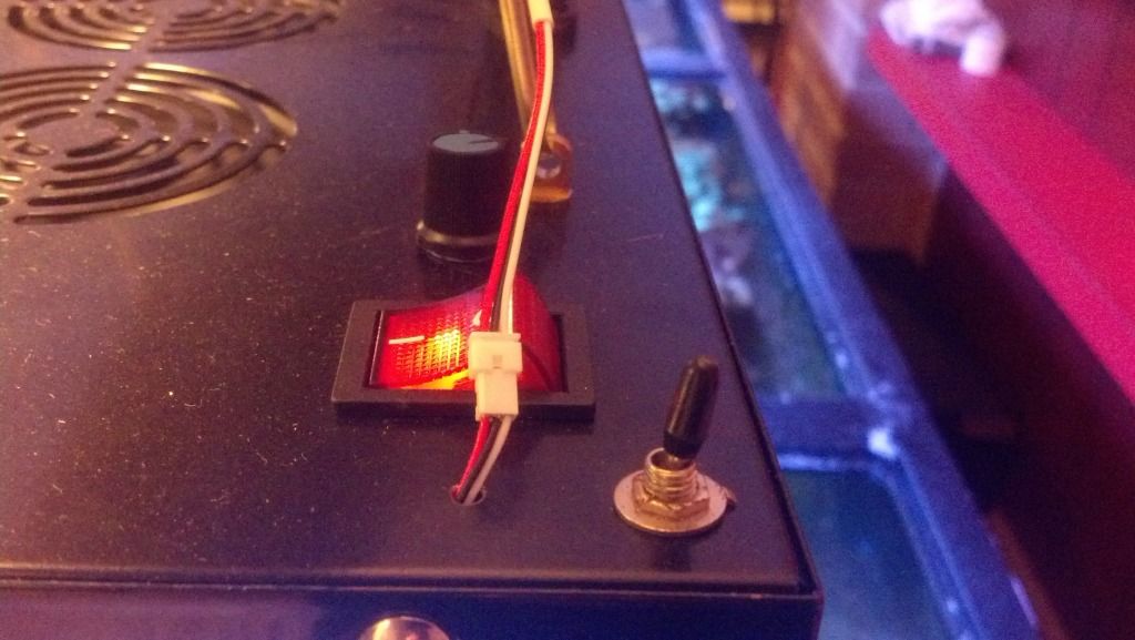
One of the things I definitely didn’t want was to have ONLY arduino control. I like having the knobs in case friends come over or I’m selling frags and people want to see the corals under different lighting than whatever is on at that time of day. So I added a switch to each channel to toggle between knob control and arduino control. That way I don’t have to get the computer out and upload new code any time I want to see a different spectrum.

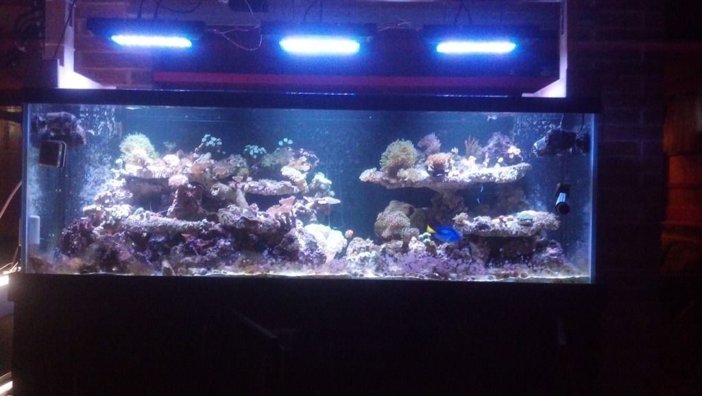
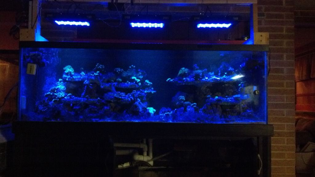
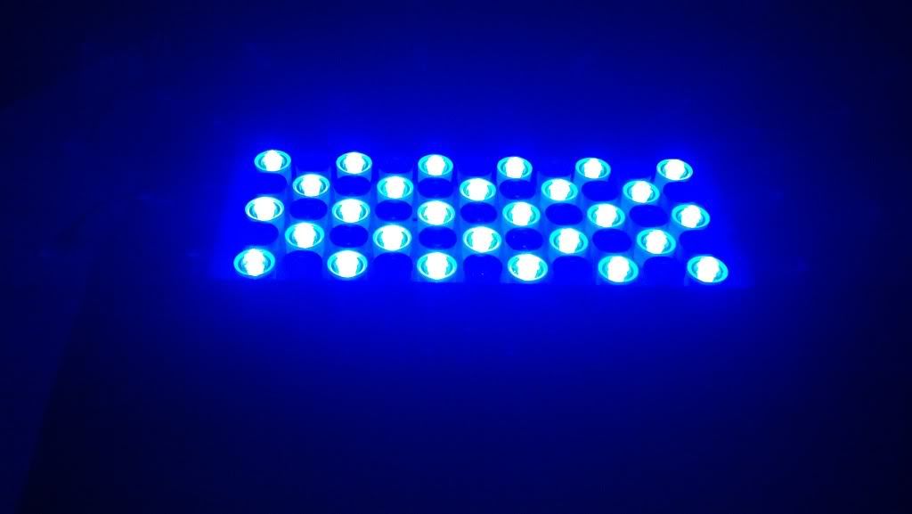
Here are some pics of the tank. I’m starting the fixtures 7" off the water surface at 10% power, running 4hrs of whites and 8hrs of blues. I’m having some bad shadowing problems right now and am open to suggestions. I’m considering pulling the optics off some of them.

Very nice B! What is the cost of all the components roughly? I might have to try this with my ReefBreeders sometime.

Total cost:
arduino pro micro $19.95

Real time clock $14.95

2x 5V DC relay $9.98 (you can get these cheaper somewhere else)

5V regulator $0.51
http://www.digikey.com/product-detail/en/SPX1117M3-L-5-0%2FTR/1016-1849-1-ND/3586566
2x NPN transistors $0.68
http://www.digikey.com/scripts/DKSearch/dksus.dll?Detail&itemSeq=135005512&uq=635122374330929101
2x 10K resistors $0.16 (connect to transistor base to prevent it from burning it up)
http://www.digikey.com/scripts/DKSearch/dksus.dll?Detail&itemSeq=135005693&uq=635122374330929101
Project box ~$5, but everybody has something in there house they can use
10-15V DC power adapter ~$5, but these are so ubiquitous I wouldn’t recommend buying one
2x Dual Pole on-on toggle switch $8.98/fixture $26.94 for 3 (this is optional)

I had most of this stuff already, but if I were to buy everything it would cost $83.17. I only bought the arduino and RTC so I only spent $34.90 + shipping. It’s important to note that this arduino is capable of controlling your entire tank, so it might seem a lot for a stand-alone LED controller, but considering what this thing can do, it’s not that bad.

A minimalist approach would be to use a couple 555 timers to generate the pwm and count the pulses to estimate the time of day. This would eliminate the arduino and RTC. You could also not add the switches to each fixture. Assuming you could find some kind of plastic box to put it all in and a power adapter, you could feasibly make this for under $10, but it won’t have all the bells and whistles.

sorry to resurrect this!

Bnelson, do you think it would be possible to convert LED fixtures that only use pots to dim to accept a 0-10VDC signal?

My drivers need to sink the 10v that the driver provides. IDK about other fixtures, but that’s how mine work. I’m assuming you’re asking bc you want to connect it to your apex right? If your apex can send a pwm signal across the full bandwidth (0-100% duty cycle) then you can do the same thing I did. If it only sends a narrow band like a servo controller then it wouldn’t work.

[quote=“bnelson, post:5, topic:6633”]
…If your apex can send a pwm signal across the full bandwidth (0-100% duty cycle) then you can do the same thing I did. If it only sends a narrow band like a servo controller then it wouldn’t work.[/quote]

“Boy, I didn’t understand a word you just said.” - Chicken Farmer, Napoleon Dynamite.

are we frying fish yet?

::rofl:: I was lost in the first sentence ::rofl::

I’m pretty sure if it dims with a pot you can dim with a rkl or apex. But the other controllers use another way, pwm I think

:GEEK:
I was thinking more along the lines of a building automation controller since I have easy access to them.

They output 0-10vdc on their analog outputs. I was wondering if I could just use a digipot that follows the same resistance range as the pot that’s built in.

You could use a digipot, a trasistor, or direct control From your analog outputs it depends on what drivers you get with your leds. Bottom line, you have options. What controller are you thinking about using?

Probably a tridium jace once one becomes available.

My drivers do not have any type of connection for external control.

So are they dimmable? If they are, then you can wire up some kind of control. I did mine through a dual pole switch so I could toggle between on board control (the pot) and external (my arduino).

Yes they are dimmable. What I meant to say is that there are no separate contacts for a controller like on controllable ballasts.

Id have to wire it into the built in pots. Wish these things came with a ladder diagram.

If you guys come up with a “simple” thing to make a chineese dimmer knob led compatible to an analog 0-10v apex unit LMK. I’d pay for someone to make my leds like that. That is the biggest reason I am considering a higher end fixture.

Scott, it seems so simple in theory.

Buy a digipot that accepts a 0-10vdc signal and outputs the resistance range of the built in pot.

I hooked a meter up to the pot at one point but I forget what the resistance range was.